Domain Driven Design Diagram Tools
Domain-Driven Architecture Diagrams
![]()

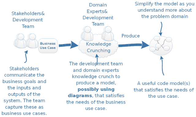
Domain-Driven Design is about creating shared understanding of the problem space that is reinforced ubiquitously via conversations, code and diagrams. DDD's Shared understanding enhances synergy and alignment, increasing the ability to deliver value sustainably — ideally over the lifetime of a product.
As I most recently attempted to justify at the London Women Who Code Intro to DDD Architecture workshop, the architecture of a system, expressed via diagrams, is a profitable avenue for reinforcing DDD's shared model.
Highlighted in red: where architecture diagrams can be advantageous using a domain-driven approach.
Diagram modified and borrowed from Patterns, Principles and Practices of Domain-Driven Design published by Wrox
One idea I've used on the last few projects is a general framework for creating Domain-Driven Architecture Diagrams. When focusing on the strategic aspect of Domain-Driven Design, this framework is a useful starting point for mapping your understanding of the domain onto a proposed software architecture.
In this post I'll outline the framework. It is derived from Simon Brown's exceptional C4 framework which has been a career-accelerating revelation for me.
System Context Diagram
I believe it's vital to give people a high-level overview of the system — the users, the use-cases, the major internal systems, and essentially those risky external dependencies out of your control that need to be monitored. In C4 nomenclature this is the system context diagram which we can use for documenting our domain-driven architecture.
This diagram is unimaginably effective at engaging non-technical stakeholders in project and program level issues that are potential show-stoppers or critical blockers. This diagram is also perfect for acclimatising technical and non-technical newcomers to a project.
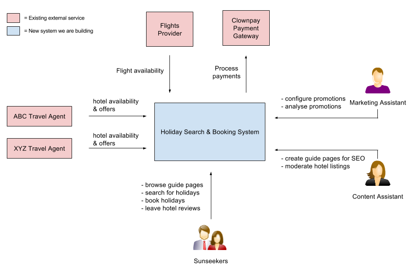
We can use the system context diagram to reinforce our shared model by using ubiquitous language to list users, names of systems, and interactions as shown below.

A system context diagram that shows high-level information, abstracting away bounded contexts.
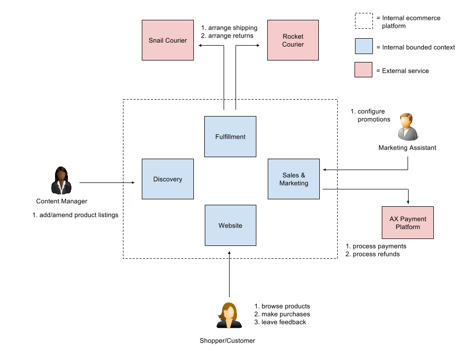
If you can maintain clarity, then it's fine to show your bounded contexts on the system context diagram as below. Note how, in comparison, the diagram above abstracts away bounded contexts and presents the new system as a single concept to keep the diagram clear.

For systems with few bounded contexts, it can be easier to show them the system context diagram
My threshold is about 7. If I have more than 7 boxes on a diagram, it's probably showing a bit too much detail so I'll avoid showing the bounded contexts at this level.
Bounded Context Map
Traditionally known as the context map, but qualified here as the bounded context map to completely disambiguate from the system context diagram, this high-level visualisation shows the relationship between bounded contexts so that everyone has a clear understanding of the internal landscape.
Team relationships, communication patterns, integration strategies, and cross-team dependencies are all useful types of information that can be accentuated with a bounded context map as expertly explained by the affable Alberto Brandolini http://www.infoq.com/articles/ddd-contextmapping.
Many of the organisation's I've spent time at lack a systemic view of how their bounded contexts and teams relate to each other. This can be damaging for everyone, especially when you are a developer who doesn't understand how your part(s) of the system fits into the whole, leaving you helpless at explaining end-to-end processes to business stakeholders or optimising for system-level benefits.
An example (bounded) context map taken from Patterns, Principles and Practices of Domain-Driven Design published by Wrox
A bounded context map is one possible solution. As shown above, It can be high-level, low maintenance and low effort. It can massively improve shared understanding, whilst accentuating inefficiencies and organisational issues, so you can catch them early with the help of technical and non-technical people.
For systems that use asynchronous, event-driven communication, and each bounded context is owned by a single team, with no shared dependencies, the bounded context map is less effective but can still be worthwhile. You may be able to express the important information on the system context and business use case diagrams and skip this one. But be careful.
Bounded Context Deployables
At some point you need to validate your software architecture with technical realities and constraints. This is the purpose of a bounded context deployables diagram.
Which services (will) exist inside a bounded context? How do they interact? What are the major technology choices? This illustration is used to answer those questions.
Usually, one bounded context deployables diagram per-bounded context is the most effective approach, leaving each team to decide if they need/want one and in control of maintaining it.
This diagram is important for setting a clear vision of what your team is going to build, for getting new team members upto speed, and for educating outside teams, like the ops team, about the workings of your deployables. This diagram can also be useful for highlighting knowledge that can be shared around an organisation or duplication that can be avoided.
In C4 nomenclature, this is known as the containers diagram. However, I think we can be more specific in DDD — especially when the word containers is so deeply associated with docker and microservices now.
Below is an example bounded context deployable diagram showing a bounded context and the units of deployment it is composed of. This is taken from the samples in my Intro to Domain-Driven Design Architecture Workshop.
Too much design up-front? Not in my experience. This diagram evolves as our understanding does, providing the entire team with a clear picture of what we are trying to build whilst accentuating certain classes of problems (e.g. compatibility) at an early stage.
Business Use Case Diagrams
Part of a Domain-Driven Design strategy is coordinating bounded contexts to carry out full business use cases. Yet if each bounded context has it's own diagram, we can't clearly see this end-to-end picture. This is why I create dedicated, end-to-end diagrams of each important use case.

Creating diagrams with domain experts expressing full business use cases as a precursor to implementation increases confidence. This illustration is borrowed from Patterns, Principles and Practices of Domain-Driven Design published by Wrox
The most expressive name I can think of is business use case diagram, since that is exactly what I am trying to communicate. And that's how I refer to them in my head. Perhaps even full end-to-end business use case diagram would be better.
In Patterns, Principles and Practices of Domain-Driven Design, I referred to this kind of diagram as a component diagram, taken from the C4 framework. The diagram is shown below and is used to demonstrate events flowing through an event-driven architecture.
The payment rejected use case diagram that I referred to as a component diagram in Patterns, Principles and Practices of Domain-Driven Design published by Wrox
This diagram shows the payment rejected business use case. I referred to this diagram as a component diagram in Patterns, Principles and Practices of Domain-Driven Design, but regret that decision a little due to the ambiguity of the term component.
I labelled this as a component diagram because each arrow is an event, and each event has it's own component that publishes it. Additionally, the diagram avoids technical details, so it's not a containers diagram either. In the book a component is the unit of deployment.
As Simon Brown says, and I've come to realise myself over the years, the term component can mean anything — a class, a module, a unit of deployment, an architectural abstraction — there's an even a JIRA field for component. So I've decided it's best to just not use the term component.
So what instead? Well in these types of diagrams I want to show how bounded contexts work together to carry out full business use cases. So how about business use case diagrams, named after the use case they are illustrating?
Domain Concept Diagrams
Every complex domain has intricate business rules, policies and workflows. Before you can model them in code, you need to work with domain experts to create strong neural pathways, giving you the confidence to implement.
In these scenarios, diagrams are useful. Aim to work with domain experts to create technical-jargon-free diagrams in the language of the business that act as a blueprint for creating a domain model highly-aligned with the problem domain.
Simon Brown refer's to these diagrams as components — below the level of the deployables but above the level of classes. I refer to them in my head as domain concept diagrams, since I just want to express domain concepts as clearly as possible using the ubiquitous language.
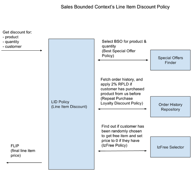
Below is an example of a domain concept diagram I created as an example for the Intro to Domain-Driven Design Architecture Workshop.

This domain concept diagram shows how the Line Item Discount Policy is calculated in an ecommerce domain. This is in the language of the business; BSOP, RPLD, FLIP etc are all entries taken from the ubiquitous language, though it does contain a few technical necessities like a repository.
How many of these diagrams should you create? It depends. Sometimes you can create them on the whiteboard and throw them away once you've written the code. My heuristic is to maintain domain concept diagrams for the fundamental policies that are key to a business's value propositions or concepts that cannot be fully expressed in code.
Just a Guideline
Acclimatising to a new problem domain takes time. Words can have specific meanings with only a loose connection to their dictionary definition and stakeholders can have wildly-differing opinions about what is important to the business. Yet, greenfield or brownfield, when you're dropped into a software project you are expected to deliver.
Rich visual information that clearly communicates important technical and non-technical information, such as key business differentiators, organisational constraints, and the proposed/existing technological configuration is essential for getting upto speed.
I use Domain-Driven Architecture Diagrams to satisfy this need and I encourage you to do the same. But it is just a guideline for quickly understanding what information is needed, how it can be clearly presented, and to whom it should be presented to.
If you want to skip some of these diagrams or merge them together, that's fine. I only recommend creating diagrams if they give you an advantage.
I also wholeheartedly recommend you learn about Simon Brown's C4 model of sketching, which provides sublime guidelines for keeping diagrams clear and expressive.
How to Practice and Improve?: Run a Workshop
If you want to improve your diagramming skills, or test out the Domain-Driven Architecture Diagrams concept, why not run your own workshop? You can use the materials from my Intro to Domain-Driven Design Architecture Workshop as a starting point if you like.
If you get stuck you can email me or if you want some help I might be able to pay you a visit and run the workshop for you. But try to be brave and have a go yourself. Please let me know what works if you do try or any improvements you can suggest.
Domain Driven Design Diagram Tools
Source: https://medium.com/nick-tune-tech-strategy-blog/domain-driven-architecture-diagrams-139a75acb578
Posted by: arnoldtherstion1975.blogspot.com

0 Response to "Domain Driven Design Diagram Tools"
Post a Comment